# AutoCAD Civil 3D - Cross Sections
# Cross Section Sheets
Are you sick of fiddling around wtih sections for JHG engineers? Behold a better way of creating and printing section has now been set up.
See below for instructions on how to use this feature in AutoCAD Civil 3D.
Assuming you have made a set of sample lines, you know how to create sections and you are now ready to create sections.
Step 1 - Determine your sheet size and annotation scale. A3 is the preference here with 1 section per sheet but there could be instances where you have a alot of sections and it could be beneficial to have multiple sections on each sheet. Templates have been set up for Scales 1:100/1:250/1:500/1:1000 for all Sheet sizes A0/A1/A2/A3
AS a rule of thumb, see the table below for A3 Sheets on the widest sample line width that will not fit on a single page:
| Annotation Scale | Widest Sample Line Width |
|---|---|
| 1:100 | 35m |
| 1:250 | 85m |
| 1:500 | 175m |
| 1:1000 | 350m |
It can be beneficial to trial a few scales first to determine the sheet size and scale you would like to use. Remembering you could need some space for annotations and dimensions as well.
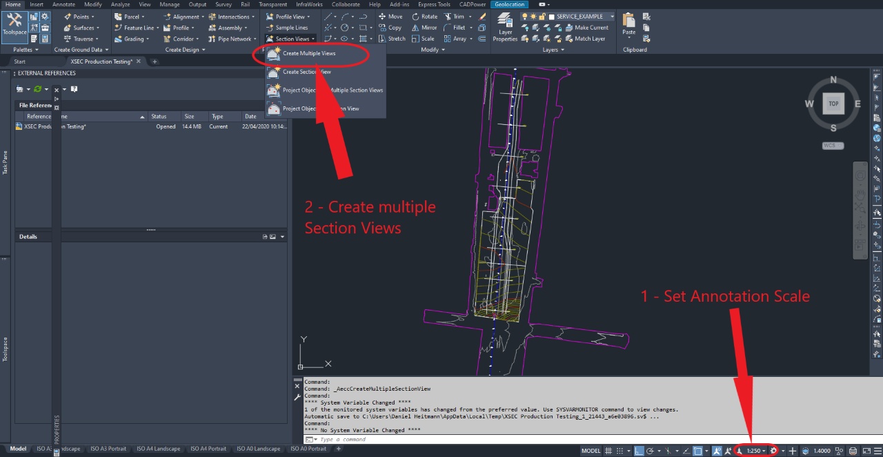
Once you have determined your Annotation Scale (1), set it in Model Space and then procees to create Multiple Section Views(2).
# Step 2 - Create Multiple Section Views - General

This simply determines the alignment, sample line group and the view style to use. Alignment and Sample Line Group are dictated by the project you are on. However, the prederence for Section View Style is as listed above ANZ_(Rd) X Section plot 1X - (No Vertical Exaggeration), this style is preferable to use because there is no exagerration to the section meaning, what you measure on the screen does not neeed to be scaled.
Click Next
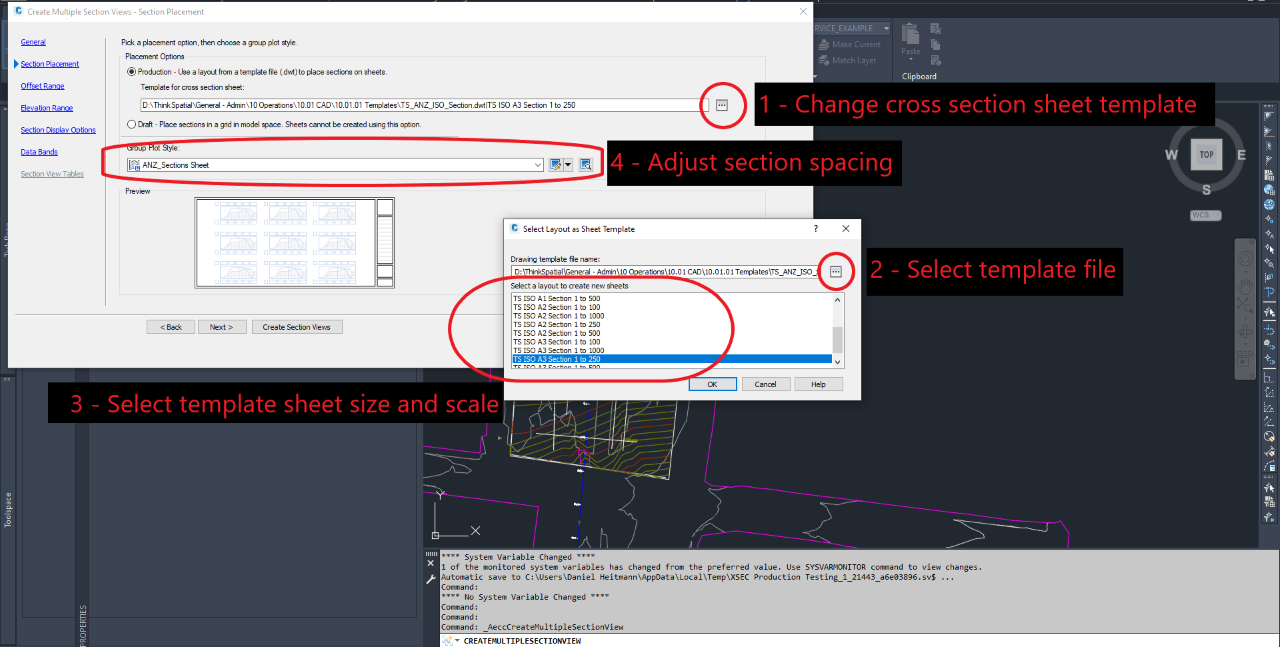
# Step 3 - Create Multiple Section Views - Section Placement
This step is where the sheet sizes and section spacings are set Click on the 3 dots in Placement Options (1), this is the change sheet template. Click on the 3 dots in Select Layout as Sheet Template (2), select TS_ANZ_ISO_Section.dwt which is found in: D:\ThinkSpatial\General - Admin\10 Operations\10.01 CAD\10.01.01 Templates\TS_ANZ_ISO_Section.dwt. Then select the desired shett size and scale (3). In this example it is A3 at 1:250. Section Spacing (4) is determined by the group plot style. This is used for the distance between sections and the page borders. ANZ_Sections Sheet is the default and works well. When there are multiple sections per page you may need to modify this spacing to allow for annotation and object labels.
# Step 4 - Create Multiple Section Views - Offset, Elevation, Section Display Options, Data Bands
Create this as you would normally do for sections and then select an appropriate place.
# Step 5 - Create Section Sheets
Select one of the Green and Yellow Boxes created from the section (1), then in the ribbon click Create Section Sheets (2). Select Section View Group (3) is only applicable if you have multiple alignments, sample lines and section views. Layout Settings (4) determines the names of each layout tab created. Name the sheet set (5) and set where it is to be saved (6). This should be in the same folder as where the drawing is saved.
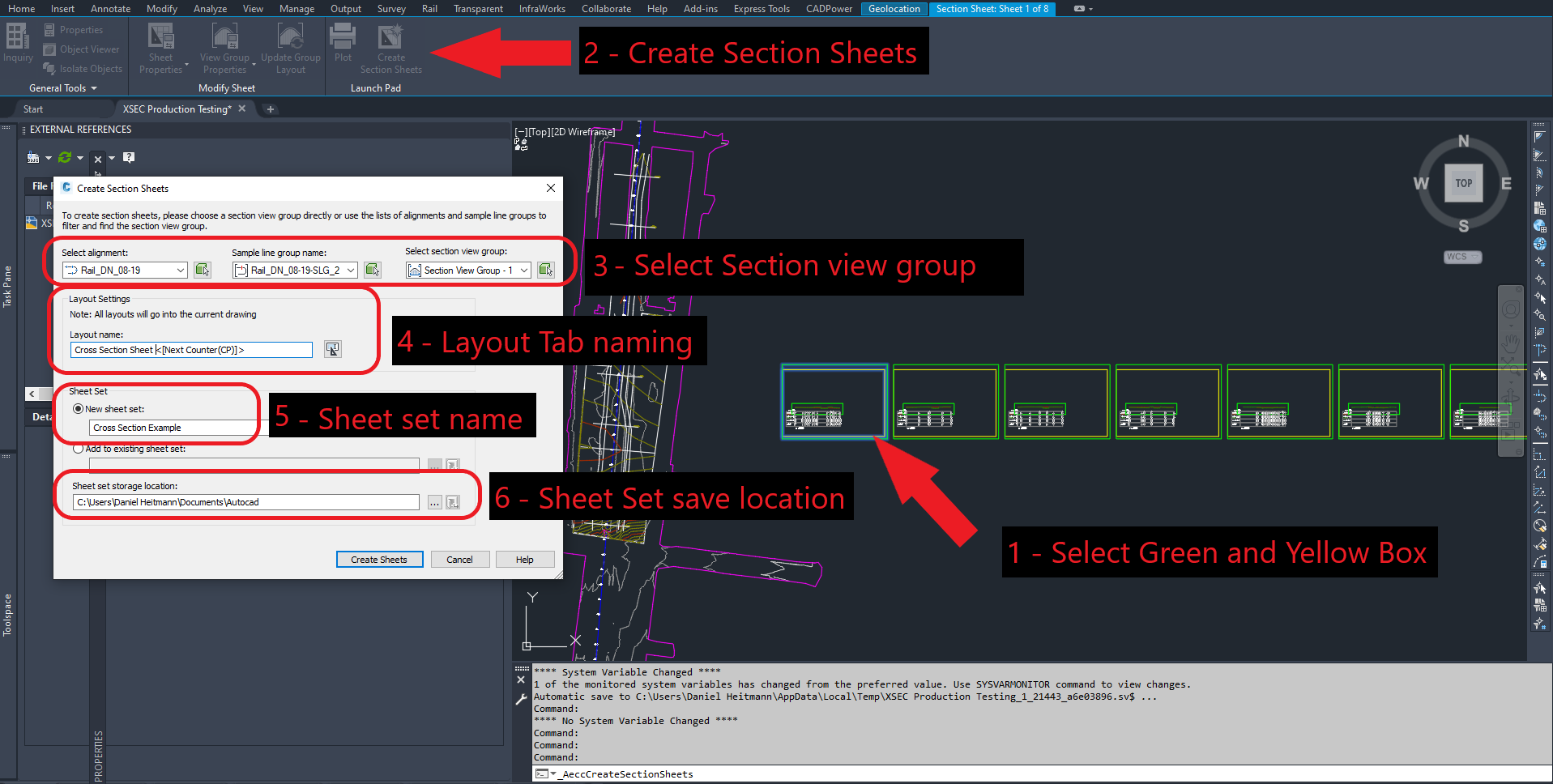
Click Create Sheets, a box will then prompt for the file to be saved so click OK.
TIP
FYI - The green and yellow boxes show the sheet size (GREEN) and the viewpoint (Yellow)
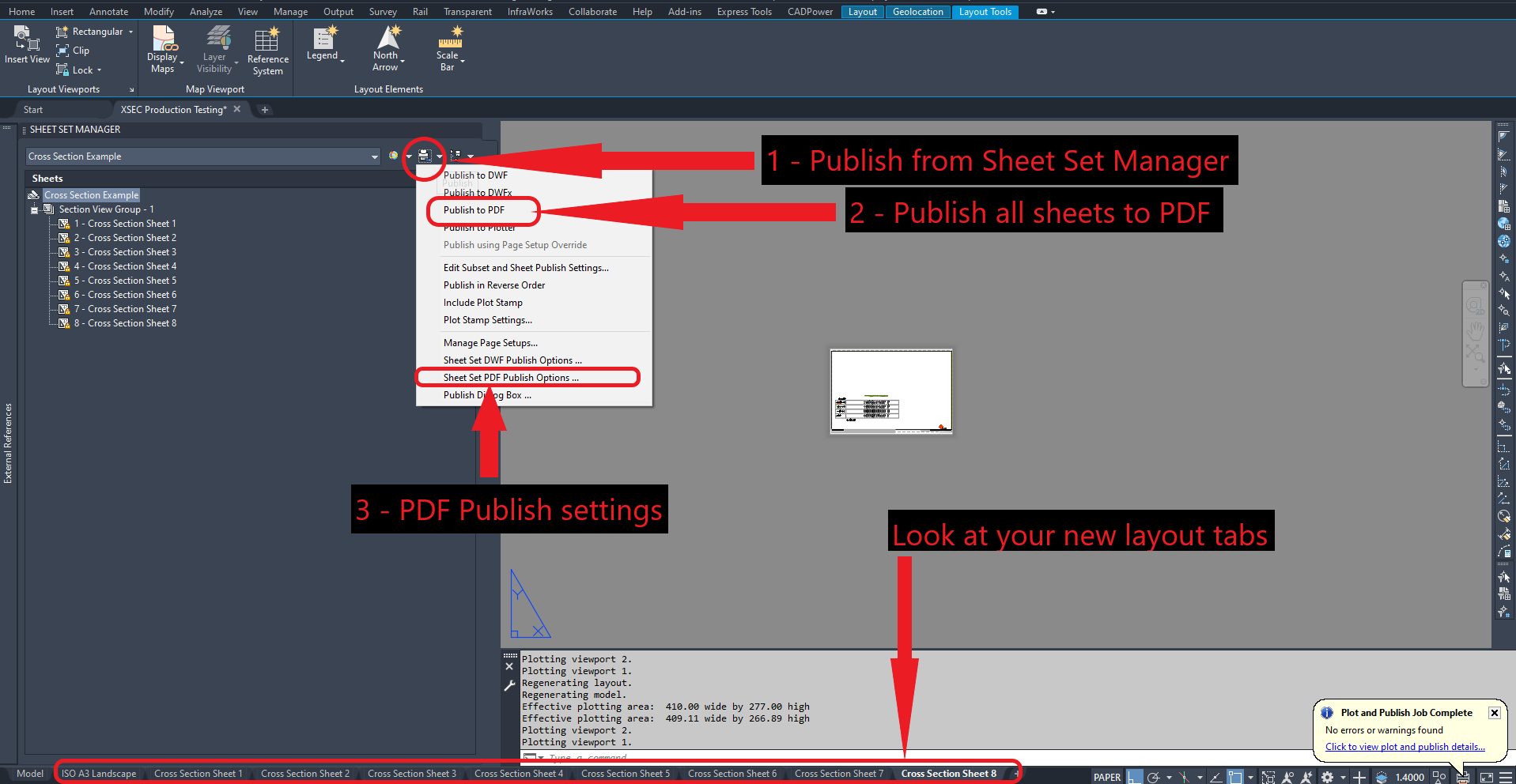
# Step 6 - Publish (print) your sections
Taaa Daaaaaa. Your new layout tables are created!
After you have added labels, dimensions and annotations you are ready to print. If the Sheet Set Manager is not open, type "SHEETSET" in the command bar. (1) Publish from the Sheet Set Manager and then select Publish to PDF (2). The sheets are set up to PDF coorectly, but you will need to change the location where the PDFs are saved. This can be set in Sheet Set PDF Publish Options (3).