
# Feature Survey
# Before You Begin
You will require the following before you beging this work process:
# Software
• Trimble Access
• AutoCAD Civil 3D
# Hardware
• Total station
• Tripod
• Mini Prism
• TSC7 controller
• Prism Pole
TIP
If possible use the SX10 to complete a feature survey. This allows you to complete a scan at the same time and add additional data that could be missed or add Overhead powerlines.
# Controller Setup
It is important to correctly set up your job prior to commencing the feature survey.
On the TSC7 Controller select ‘new job.’ Enter your initials followed by the date in reverse order (yymmdd).
Next, select the required template and coordinate system for the project.
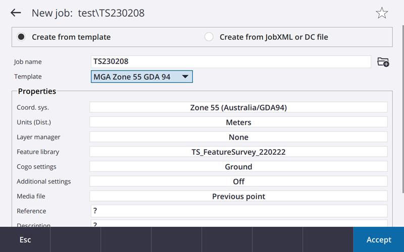
If there is a control file for the job, this can be linked under the layer manager tab.
Under ‘Feature Library,’ select the codes list relevant to the project, in this case ‘TS_FeatureSurvey_220222.’ This holds the relevant codes and attribute information needed to conduct a feature survey.
Once all the project settings are input, press accept.
# Setup the Total Station
Prior to surveying features, either set the total station up via ‘Resection’ or ‘Station Setup Plus’ and be sure to follow all measures of good practice.
# Measuring Features
Once the instrument is set up, recording of features can begin.
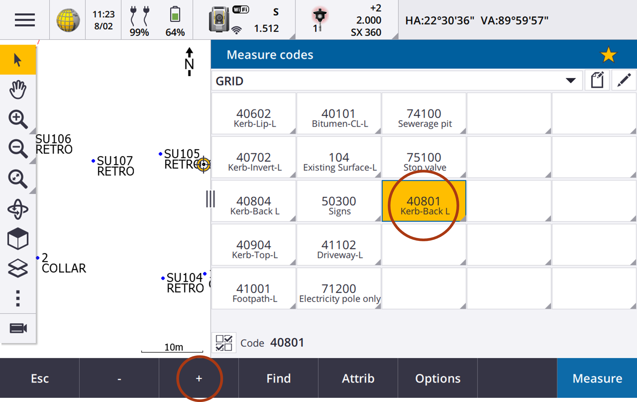
This can be done through the ‘Measure Codes’ window found in the Hamburger > Measure > Measure Codes. The following screen will appear.
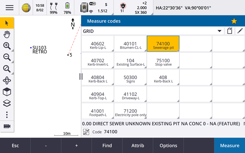
You can create your own grid and populate it with relevant codes to the feature survey. Above are some common codes for a streetscape feature survey. To enter a code, tap and hold down a cell. This will bring up the code list as follows.
You can search for the desired code in the search box. Below shows that there are two types of codes: single point, and line (denoted by the ‘L’). Most features should be surveyed as line.
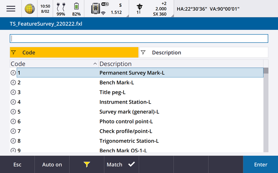 Seearching within the Feature Code List
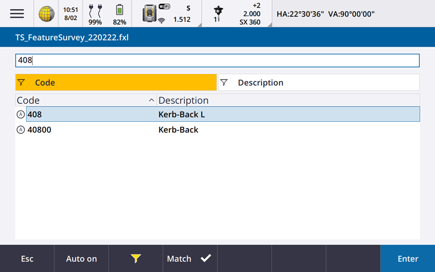 String and Line Types, Strings are will have 3 numbers whearas point codes end in 00.
To create a line by stringing points, press the plus button in the lower ribbon whilst the desired code is highlighted. This moves incrementally through the line numbers. You’re now ready to begin capturing features, to do so press measure.
TIP
Detailing Various Features
There are some features that have a specific way of being captured.
• For arcs such as kerbs/roads, capture five points per arc.
• For rectangular pits, capture the four corners of it and close the line.
• For large poles such as electricity poles, capture 3 points around the circumference to create a circle.
• Where unlisted features are surveyed, please take a picutre of them as an attribute. This will help deterimine them at a later date.
# Attributes
All codes have have at least 2 common attributes: COMMENTS and SC.
COMMENTS is used to add additional information that could be helpful to users of the end DWG file. It is stored as both Property Set Data within the CAD object and produces text when proccessed within AutoCAD.
SC stands for Special Code and are based on GeoCivil Codes. They can be used to reduce the amount of time processing your data.
Special Codes have are detailed later
There are other codes which have additional attributes such as trees and existing services. These will be detailed in further within 03 Codelist.
# Special Codes
Special codes are commands that perform various functions. They can be input to the attribute window above.
| Special Code | Function | Code | SC |
|---|---|---|---|
| 20 | Close Line | 18001 | 20 |
| 17 | Create Arc Based on 3 Points | 18002,18002,18002 | 17 |
| 18 | Draw Circle with radius started after | 180000 | 18 0.2 |
| 16 | Join 2 Codes, second code is the start point | 18003 | 16 18005 |
# Feature Survey Workflow
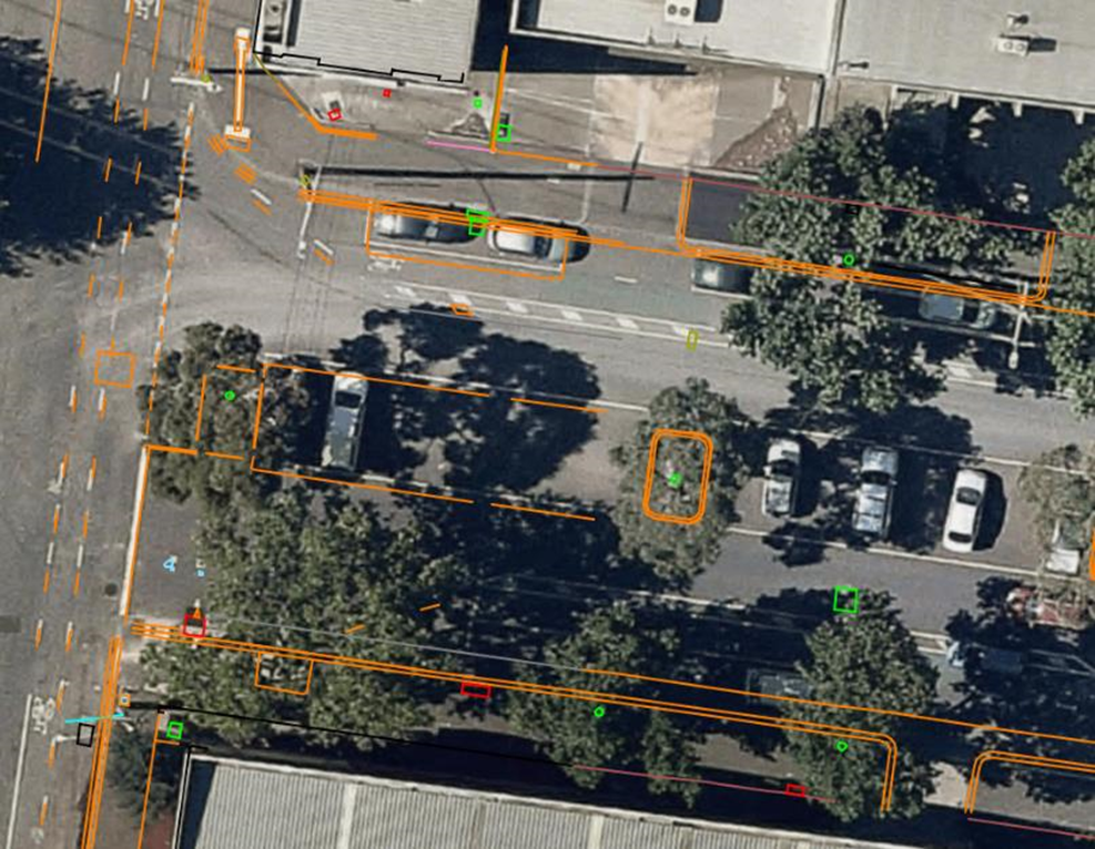
Quite often there is a large amount of data required to be captured. Thus, it is important to develop a logical workflow to ensure no features are missed. A way to approach a feature survey such as the streetscape in Figure 7 would be to treat the street as a cross-section. A basic cross-section would be;
- Footpath
- Back of Kerb
- Top of Kerb
- Invert of Kerb
- Lip of Kerb
- Centre Line of Bitumen
- Lip of Kerb
- Invert of Kerb
- Top of Kerb
- Back of Kerb
- Footpath
This would be completed every five metres along the streetscape as well as capturing any other features that you come across.
# Surveying other features
When conducting a feature survey, it is important to survey all pits, posts and valves associated with utilities. Most of these features are surveyed at ground level and will be used when creating a surface. If a service is not surveyed at ground level, and the name isn’t obvious like Overhead Powerlines, make a notation to not include in the surface to avoid confusion. Single point features, like stop valves, can be picked up using the feature code followed by 00 to create a point. For example, a water valve would be 31000. Square pits, or utilities where a concrete surround is surveyed, can use the 20 code to connect the last point surveyed with the first point surveyed with the same feature code and string. For example, to survey the four corners of a drainage pit and close the square you would use 19301 on the first 3 corners and then 19301 20 on the last corner. The next pit would then be 19302 etc.
TIP
Utility features surveyed within the feature survey require more attributes. These will be integrated into the service master by the utility data manger
# Connecting to Australian Height Datum (AHD)
Where no traverse has been undertaken and GNSS control is being used you will need to connect into AHD.
Place appropriate control into the ground (Dumpy Pegs, Star Pickets, Rivets etc) and observe control point for 3 minutes. Place 3 GNSS control marks in the ground so that a resection can be performed.
At the completion of adding in control marks you will then check GNSS against PSM Survey Marks.
Check against 3 AHD marks within the area. Discard any outliers, average the difference between them and then adjust the placed control marks.