
# Utilities
# Background
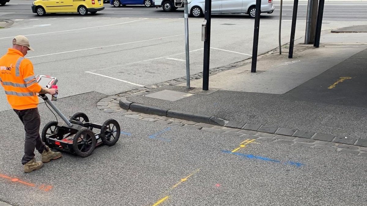
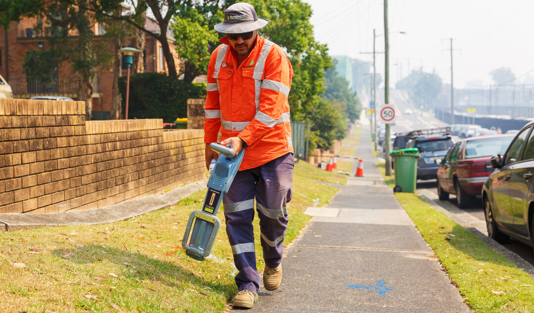
Utility locators use specialized equipment such as Electromagnetic Radiodetectors, Ground Penetrating Radars to detect underground services. Surveyors will work with the Utility Locators to generate a 3D CAD model of the services within the area. At the start of a project the Service Master will be all Quality Level D data. The engineering team will investigate services which will impact certain aspects of the project design. As better quality service information is added the model is improved. AS5488.1 is the Australian Standard for Subsurface Utility Information and it designates 4 different quality levels for underground utilities.
# Quality Level D
Location is indicative.
Most commonly known as DBYD (now BYDA). This information has been either provided digitally from the utility owner or digitized from plans that the utility owner has provided. The location of these services within the service file are indicative only.
# Quality Level C
Location is indicative.
This is typically given to fill gaps between features so that it indicates there is an underground service within the area but the depth and location is still unknown. Most commonly it is Pit to Pit to show there is a service present however the location and depth is unknown.
# Quality Level B
**Horizontal Tolerance ** +/-300mm
Vertical Tolerance +/-500mm
Previously known as TRACE data. The locator will generally connect directly to the service or conduit and then using the applicable equipment to find the alignment of the service underground. The locator will spray out the alignment, estimated depth, conduit diameter and material.
# Quality Level A
**Horizontal Tolerance ** +/-50mm
Vertical Tolerance +/-50mm
Previously known as DIRECT data. It is the best quality level of service locating and is when the service is exposed entirely. It is typically exposed by Non-Destructive Digging (NDD), which is high pressure watergun and a vacuum truck to dig exploratory holes to visibly locate services. When the service is found, we will take a direct measurement on the Top of the service and survey the extend of the NDD hole. Utilities are only Quality Level A where it has been exposed.
# Ground Penetrating Radar
Typical Accuracies
# Electromagnetic Radiodetection
Typical Accuracies
# Drainage Pit Surveys
Often drainage pit surveys are done separately from the feature survey as they usually require opening the lids of the pits and surveying the pit base and pipe inlets and outlets along with their dimensions. Specialised tools are used to open pits and correct techniques should be used to avoid injury. Also note that pits can be defined as confined space and require special training and permits to enter. When the pit lid is removed, note down the depth to invert, Spray in green the pipe diameter, material (if known) and the depth to invert. Where invert is not known the pobvert can be measured and invert assumed based on pipe diameter.
An indicative direction should also be surveyed to help connect pits up and determine direction of flow. When it is known that two pits connect, these two inverts can be surveyed with the same feature code and string number so they are automatically connected when processing. See below for an example of connected pits and some with indicative directions.
Diagram of Pits - Indicative direction and conected pits
# Field Process
# Introduction -> Codelist Changes - Survey of Utilities
The survey codelist has been updated for 2023. In particular there have been changes to the utility attributes The purpose of the updates is to provide a clearer understanding of the utilities present and the information available in the area of interest. Most of the actual numeric codes used in the field have not changed.
# Attributes changes
Some attributes have been removed from pits and surface features so that those that aren’t required are no longer listed. See examples below.
The naming of some attributes has changed to better reflect their meaning or a change in the way we record the utility data.
| Old | New | Note |
|---|---|---|
| Item | Feature | This is just a name change, it describes the physical feature being surveyed. Pipe, pit or cable etc |
| Quality | Method | This change means there will be no need to interpret the quality level of the location method. More details below. |
| Size | Size-Bank | Recording of multiple conduits (banks) for existing utilities is always a challenge for survey codelist. With codelist updates we will be recording the bank details in a couple of ways. The Size-Bank field will be used to record a description of the bank e.g. 6x100 or 3x50 & 2X100. See below for details on recording banks. More details below |
| Sub_item | Sub-type | This is just a name change, it describes the sub type of utility |
| Type | Status | This is just a name change, it describes the status of the utility e.g existing, redundant, as-built. We have added “removed” in order to track changes once site works commence.. |
# Banks
There are 3 attributes that need to be recorded in order to model a bank of conduits. SIZE-BANK as described above is used to give a description of the conduits within the bank. e.g. 6x100 or 3x50 & 2x100. In addition there are 2 new attribute fields BANK-WIDTH and BANK-HEIGHT. These 2 fields are used to record the height and width in millimeters instead of the config attribute. Whilst it's clear that the information may not always be available in the field if it is recorded where possible it will enable more accurate modeling of banks in CAD.
The attributes BANK-HEIGHT and BANK-WIDTH can also be used to describe the dimensions of a culvert.
# Method
The method attribute is describing the method by which the utility has been identified and measured. To better represent this, Direct has been changed to Visual. Visual is to be used when a utility has been visually identified in a pit etc or surveyed as-built, Non destructive digging (NDD) has been added as a separate method so that locations where the asset has been proven can be more easily identified in CAD.
The options for methods are:
• Trace - Most utilities that are located without excavation use this method.
• NDD - Where there has been an excavation to prove an asset
• Visual - Used for when a utility has been identified at a pit.
• GPR - Ground penetrating radar is really only used for gas and water PE or PVC pipes. The utility locator will usually note where this method has been used.
• BYDA - DBYD has changed its name. This won’t be used much in the field.
• Other - Sometimes a utility locator will mark something out based on a bitumen scar or similar. They might mark this as QL-C. Anything that doesn’t conform to one on the above methods should be recorded as other with basic details given in comments.
# Sub-Type
Sub-type has been refined to more specifically describe the subtype of utility, therefore some things have been removed from this attribute, for example:
• For drainage invert will now only be recorded in the position field. And the subtype of drainage will only be gravity or pressure.
• The subtype for non fibre-optic comms has changed from coaxial to copper.
• Recycled water and fire service have been included as subtypes of water. And are no longer separate utilities.
# Rail Infrastructure
There has been a lot of confusion with identifying and recording of existing rail assets and in particular whether something is comms, electrical or signals. Where the asset sud-type is unknown we should use a basic rule of orange conduit as signals and white as comms. The sub-type of CSR can be used where these assets are combined in a bank configuration.
Also note for Victrack fibre optic assets should be recorded by sub-type Comms Fibre Optic, and owner VicTrack.
# Abbreviations
DB cable or DB is used by utility locators to identify a direct buried cable. This can be recorded with the feature attribute of cable. MT is empty E.O.T or L.O.S essentially mean the same thing . End of trace or loss of trace. Which indicates that the locator is unable to continue the trace beyond that point. E.O.R is the end of rod. A rod is a traceable rod inserted in an empty or non traceable asset. Most locators carry an 80m rod, but could also be stopped short of that distance due to blockage.
# Utility Data Manager
On NWPA projects the workflow will change with field surveyors still producing their daily DWG and correcting any errors in that file but the Utility Data Manager now responsible for inserting the daily files into the master file. As a result the utility master file held in the working folder will be a copy of the master file. Therefore any changes made to this file will be lost.
If you notice any errors in the master file contact the utility data manager with the changes required.
# Pipe Sizes
Whilst a utility locator will generally spray up the size of utilities the following may be useful when looking in pits or doing as built surveys.
Most conduit or pipe sizes are described by their internal diameters. (Although it varies by pipe size, material and specification of the pipe). The main exception to this is Polyethylene (PE) pipe. Which is described by its external size.
# Standard sizes
Electrical (orange) 20, 25, 32, 40, 50, 63, 80,100, 125, 150, 200
Comms (white) 20, 25, 32, 40, 50, 80, 100, 150, 200
Those shown in italic are less commonly used.
Smaller drainage pipes could be any size 100, 125, 150 but once you get to 225 pipes sizes increases in 75mm increments up to 1050 and then 150mm- 225, 300, 375, 450, 525, 600, 675, 750, 825, 900, 1050, 1200, 1350, 1500, 1650, 1800, 1950, 2100
# Service Attributes
| Attribute | Description | Gas Pipe located | Comms Bank Located | Water Pipe NDD |
|---|---|---|---|---|
| UTILITY | The main utility type. | GAS | COMMS | WATER |
| SUB-TYPE | A breakdown utilities based on capacity or other features unique to that utility for example Comms- Copper or Comms-Fibre Optic | HIGH PRESSURE | FIBRE OPTIC | POTABLE |
| FEATURE | A description of the feature being located or surveyed. Most subsurface utilities should be recorded as pipe. | PIPE | BANK OF CONDUITS | PIPE |
| SIZE-BANK | The diameter of the pipe in mm eg 100 or the description of a bank eg. 4x100 or 2x125 & 3x63. | 100 | 6x100 | 100 |
| MATERIAL | A list of pipe materials. In the case of a bank made of 2 or more material eg PVC and AC use MIXED | CI | PVC | PVC |
| BANK-WIDTH | Where a bank has been recorded as a single line the BANK-HEIGHT should be recorded (if known). This field can also be used to describe culvert width | NA | 400 | NA |
| BANK-HEIGHT | Where a bank has been recorded as a single line the BANK-HEIGHT should be recorded (if known). This field can also be used to describe culvert height | NA | 250 | NA |
| DEPTH | The depth as recorded by the utility locator. recorded at each point of the locate | 0.7 | 0.6 | 0.9 |
| OWNER | The owner of the utility | APA | TELTRSA | SOUTH EAST WATER |
| POSITION | The position that the utility has been measured either directly or where depth has been recorded to. | MIDDLE | MIDDLE | TOP |
| METHOD | The method used to locate the utility. See section on utility locate methods. The method informs the quality level. | TRACE | TRACE | NDD |
| STATUS | status of the asset at the date and time of the survey | EXISTING | EXISTING | EXISTING |
| PHOTO | To be used for NDD holes and any other purpose that assists in understanding. | 123456.jpg | ||
| COMMENTS | General comments by the locator, NDD crew or Surveyor | |||
| SOURCE | The CSV file name that was used to create the data. Automated field | CE20220424.csv | CE20220424.csv | CE20220424.csv |
| SC | Special codes used for field survey |
An example QLB diagram can be found [here](D:\ThinkSpatial\General - Admin\01 Guidance Notes\11 Surveying\11.01 Training\11.02.03 Utilities\Existing Services Diagram.pdf).
# Pit and Feature Attributes
| Attribute | Sewer Pit | VicTrack Pit | Water Valve |
|---|---|---|---|
| UTILITY | SEWER | RAIL | WATER |
| SUB-TYPE | GRAVITY | COMMS OPTIC FIBER | POTABLE |
| FEATURE | PIT | PIT | VALVE |
| PIT-DEPTH | 2.31 | 0.55 | Attribute not used |
| OWNER | YARRA VALLEY WATER | VICTRACK | YARRA VALLEY WATER |
| STATUS | EXISTING | EXISTING | EXISTING |
| PHOTO | 123456.jpg | 123456.jpg | 123456.jpg |
| COMMENTS | |||
| SOURCE | CE20220424.csv | CE20220424.csv | CE20220424.csv |
| SC |
# QLB – Preferred Method
Create a new Jobfile within Trimble Access using the INITALSYYMMDD format and select TS_AsBuilt FXL for your Feature Library.
Select the appropriate Template.
From the map window add in the Control Master CSV coordinates.
The locator will spray marks on the ground similar to below. They will be designated colours depending on what service:
- Purple – Sewer
- Red/Orange – Electricity
- Green – Drainage
- Blue – Water
- Yellow – Gas
- White – Comms
- Pink – Unknown
At the end point of the line the locator will note down the specific details about each service, Bank/Size information, material, owner etc.
TIP
If possible speak with the locator to get the best explanation of the alignment and any additional details that they might have.
Survey each line as a string using measure codes.
While using measure codes, select the ‘options ‘ button and make sure ‘Prompt for Attributes’ is checked.
Each time you survey a mark on the ground the controller will prompt you for the required attributes. At this stage you note down what is applicable. DEPTH will change depending on what has been sprayed on the ground. Refer to the table below for Attribute Details for Underground Utilities.
Insert Table explaining the attribute table
# QLA – Preferred Method
On the controller the method stays the same and can be used within the same job as other utility information and asbuilt surveys.
The top of the service is surveyed along with the top of trench (Code 951). Do not string between each NDD hole. You should be left with short lines within each NDD Trench.
Where there is no service found within the trench the bottom should be surveyed (Code 952).
The depth attribute does not need to be used where the service has been surveyed directly.
If the trench is deeper than 1.0m and you are using GNSS (or your pole is not long enough) you should use the DEPTH attribute to survey the service RL. Measure from the top of the trench to the top of service and enter in for the DEPTH attribute.
The utility data manager will interpret the QLA data so that it conforms to AS5488. With each NDD hole we should take a photo of the service as an attribute and the NDD hole itself.
These will then be uploaded as Points of Interest on Civillo to assist engineers and the utility data manger.
# As Built Services Preferred Method
Before conduits are buried it is important to directly survey any change in direction and record the attributes.
The feature codelist has been set up to survey each of the typical CSR sections and other proposed services.
Survey each individual conduit as strings and the top of trench. There maybe some cases where bottom of trench also needs to be surveyed.