# CSR Setout
# CSR
# Conduit Route
# CSR
# Conduit Routes
Conduit route can be setout in a multiple ways whichs is why you need to check with the contractor before setting them out.
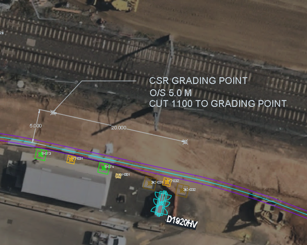
The most common is to give offset pegs of the grading, point centreline at regular intervals and every large change of direction of the route. For exmaple, 5m peg at 20m intervals and 1 peg where the route curves. The cut fill height of the grading point also has to be given.
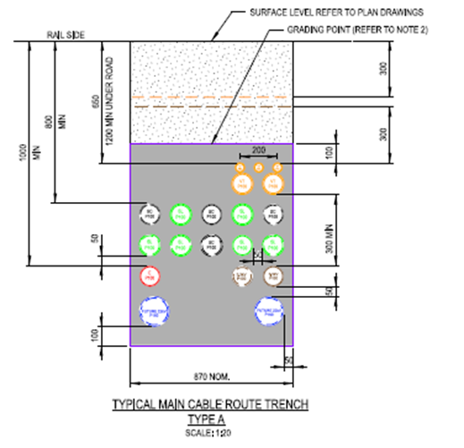
:::note The elvevation of the grading point and the top of the highest conduit are different. Usually, the grading point is 100mm higher than the top of the highest conduit. :::
Depending on the job either the total station or the GPS can be used to setout the conduit route.
Once the instrament is set up, the setout can begin.
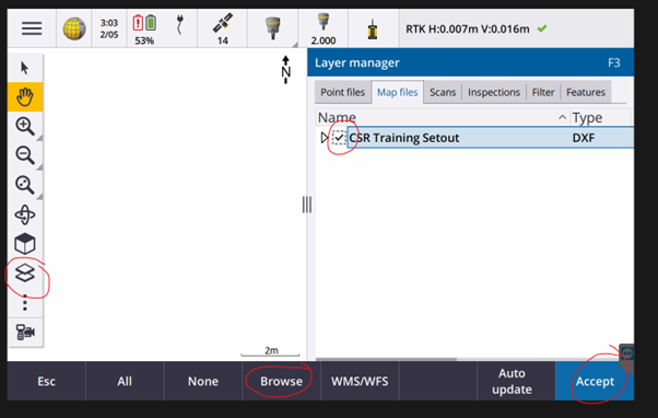
First, the .dxf file need to be imported and loaded into the job. Click the layer icon > Click browse > Navigate to the job folder > Slect the .dxf > Make sure that the dotted square and the arrrow are ticked > Click accept
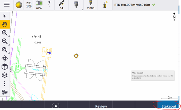
The correct setout line must be selected, once it is selected hit the stakeout button
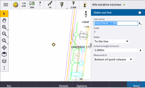
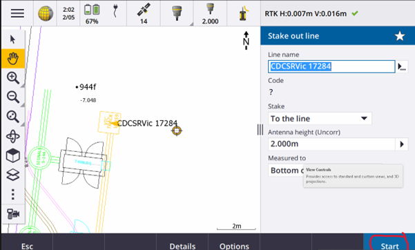
Make sure that Stake is To the line > Make sure the Antenna height are correct > Make sure Measured to is Bottom of quick release > Click Start
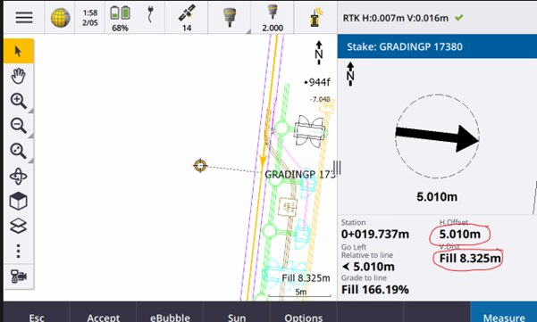
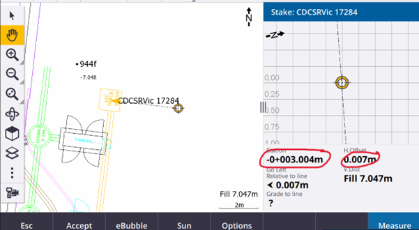
Navigate to the correct position > Make sure that H.Offset is the offset distance requried
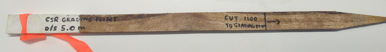
Hammer the peg into the correct position > Write down what you are trying to setout with the horizontal offset
# Pits
Pits can be setout in multiple ways which is why you need to check with the contractor before setting them out.
The most common is to give 2 offset pegs in the same direction as each other. For example, 3 and 5m. Then when they are landing the pit you may need to either spray up or peg out the kerb alignment.
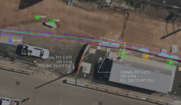
TO setout pits, add the drainage .dxf to the map window in Trimble Access. At the centre of the pit you wil see 2 lines perpendicular to each other with the corner at the centre of the pit. These give the orientations of the pit and use them to add in the offset pegs.
The line direction should be from the centre of the pit and the station line will be the offset.
After the correct line is selected click stakeout.
Make sure that Stake is To the line and Antenna Height is correct > Click Start
Walk to the position where Station is + or - 3.00m depedning on your orientation.
:::note H.Offset should be close to 0. :::
Hammer the peg into the correct position > write down what you are trying to set out with the horizontal offset.
Walk to the position where Station is + or - 5.00m depedning on your orientation.
:::note H.Offset should be close to 0. :::
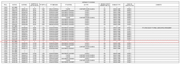
For a level typically we will give the Finished Surface Level at the top of the pit, commonly listed in the pit schedule.