
# AutoCAD Civil 3D - Profiles
# What is the difference between Profiles, Alignments and Sections?
- Alignments are the 2D design alignment used on the road, rail or pipeline project
- Think RXL in the controller
- Profiles are more typically referred to as Longitudinal Sections in PDF plans and run the length of alignments.
- Sections are referred to as Sample Lines in Civil 3D. They are at defined Chainages or regular intervals along the alignment
# Where do I use what?
- Alignments are used for everything. You will need it regardless if you are producing a section or profile.
- 9 times out of 10 this will be available to import as a XML file because it has been created for projects already
- Profiles should be used when you only need to provide 1 section or there are multiple directions in the alignment.
- Sections should be used if you need to do multiple sections and they run perpendicular to the alignment.
TIP
Need something quick? Use Quick Profile as well
# Alignments
Either Import XML or create from objects are the easiest 2 options depending on what you need to do.
Alignments will have a lot of design criteria associated with them for the curves and design speed however for surveying this is not essential.
# Profiles
After alignments have been created you can start to create a profile.
- HOME->CREATE DESIGN->PROFILE->CREATE SURFACE PROFILE
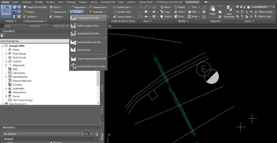
This defines the surfaces associated with the profile
- Select the alignment you have created and add the Existing Surface and Design to the profile list. This adds the existing surface TIN to the profile. Press OK when it appears in the profile list.
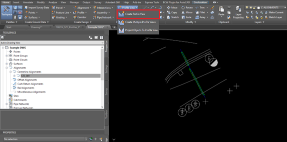
- HOME->PROFILE&SECTION VIEWS->PROFILE VIEW->CREATE PROFILE VIEW
- General – Select the alignment and change the profile view name to match the alignment name. Use Profile View Style as below.
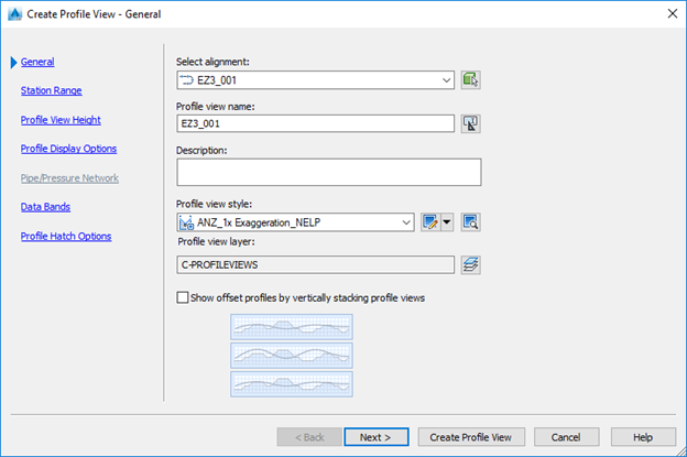
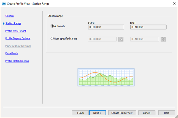
- Station Range – Automatic
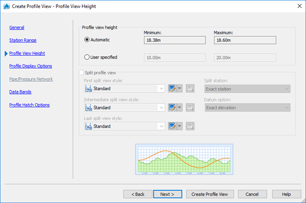
- Profile View Hight – Automatic. Can be manually to suit if there is too much blank space underneath.
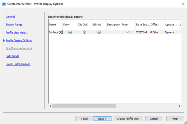
- Profile Display Options – Should show EXISTING as the data source.
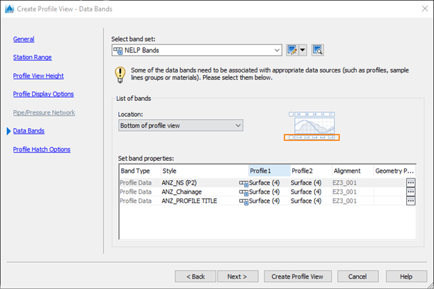
- Data Bands - ANZ Roads
- Click Create Profile View and select where the profile is to be created.
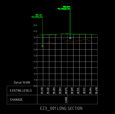
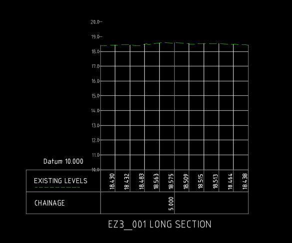
:::caution NOTE - These styles are set for an Annotation scale of 1:100 or 1:125. The profile will be similar to below :::
# Projecting data onto the profile
Services, Trench extents and Trench bottoms and other objects are needed to be shown
For this to work they will need to be 3D polylines or points. These can be converted using CADTOOLS
This can be done 2 ways as either crossings or projections. Crossings show the point where it crosses the alignment whereas projections will show the whole 3dpolyline. The preference is to use crossings rather than projections.
Type PROJECTOBJECTSTOPROF in the command line, select the services, bottom of trench string and trench outline and then select the profile. The box below will appear, use the styles below:
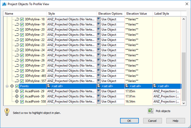
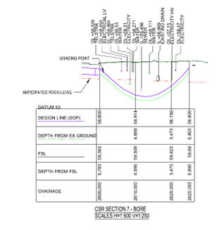
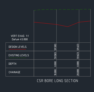
Select OK and the profile will look similar to below.
# Adding 3D data
For example if you get 2D alignment for CSR but it needs to be in 3D
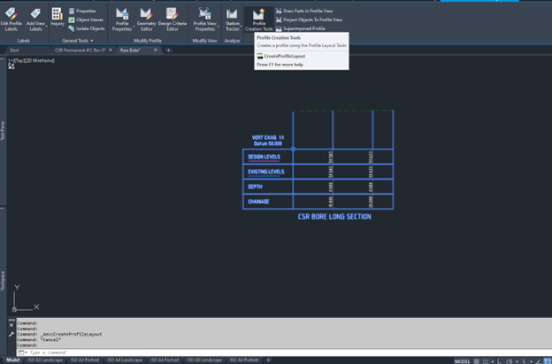
Select the Profile
Select Profile Creation Tools
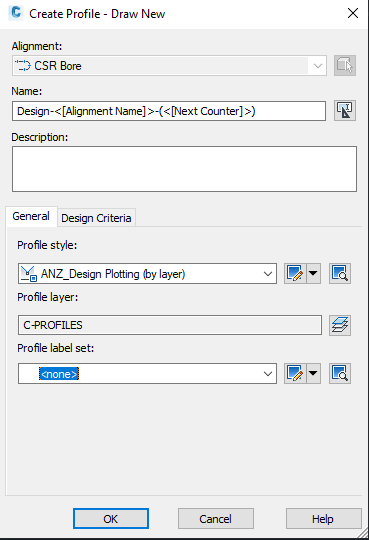
OK in the Create Profile - Draw New Dialogue box.
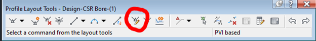
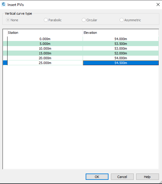
Select Insert PVIs - Tabular and then enter data in from the cross sections.
When this is created and need a 3D polyline based on the vertical geometry for setout. Follow the process below:
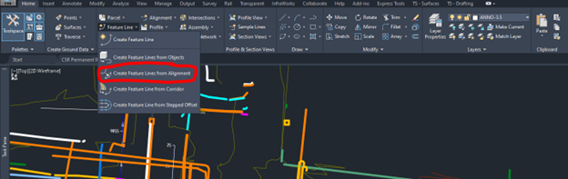
HOME -> CREATE FETAURE LINES FROM ALIGNMENT
Select the alignment and the profile you created from the list.
Then select the Featureline that is created and explode it